3D Printer Customization
Building my own 3D printer: The beginning of my journey
I was gifted a 3D printer by my brother as he knows my interests in Electronics and making as a hobby. I fell in love with it and started using it to make trinkets and toys.
Me being a tinkerer was not satisfied with just using it out of the box, decided to start tweaking its software and decided to shift from using Marlin, the default with Ender machines, to Klipper. Thus started my journey.
The printer out of the box, was a very basic machine. After my upgrades, its now, an internet-connected, remotely monitor-able, beast of a machine. It is faster, more consistent and more reliable.
The hardest challenge was sticking to using what I have and iterating, instead of focusing on bigger, better shinier. Having a solid base to work off of, helped a lot. I could tweak modularly, replacing and upgrading what was needed as needed. I ended replacing almost everything, from the motors, hotend, extruder and control board at the end, leaving only the skeleton of the original printer intact.
The internet was a big blessing to learn everything about the working of a 3D printer in every aspect. From control, to heating to motion systems. The vibrant community of 3D printing enthusiasts and their documentation was a blessing.
The printer is an elegant beast combining electronics, mechanical principles, thermodynamics and material science. I learnt a lot about stepper motors, thermal sensors, tuning and motion feedback loops through switches. The incident that led me to the realization that modding a printer is basically robotics, was when I was trying my hand at resonance damping. I was using an ADXL345 accelerometer to measure resonances on the x and y axis (This is a Cartesian bed-slinger printer) to avoid resonant frequencies during printing motions. At this time, I felt the the significance of using electronic control loops to affect mechanical motion systems. Then it clicked in my head and everything fell into place.
I achieved basically similar results to high end factory tuned machines using my own slapped together printer. High speeds, good quality prints and reproducible results. Of course the reliability was in question as I had built a lot of it myself. I have been using this printer for all my other projects as I realize that a printer exists to print for projects rather than the printer itself being the project.
Journey down the rabbit-hole of modding a 3D printer
As I kept using the printer, I saw more discussions online highlighting that while the Ender-3 V2 is serviceable, it isn’t suited for high speeds, consistent quality, or stiffer motion. I wanted to address three specific issues. The cantilevered X-axis gantry, the bed going out of level frequently, and the general speed limitations of both extrusion and motion.
The first major change was adding a second Z-axis lead screw for stability. In principle it worked, but it created a load imbalance because both screws were being driven by a single Z-motor.
To fix this, I paired the second screw with a second motor, wiring both motors in parallel on the same driver. This solved stability during printing, but created a new problem: the motors would fall out of sync after power-off because their resting positions differed.
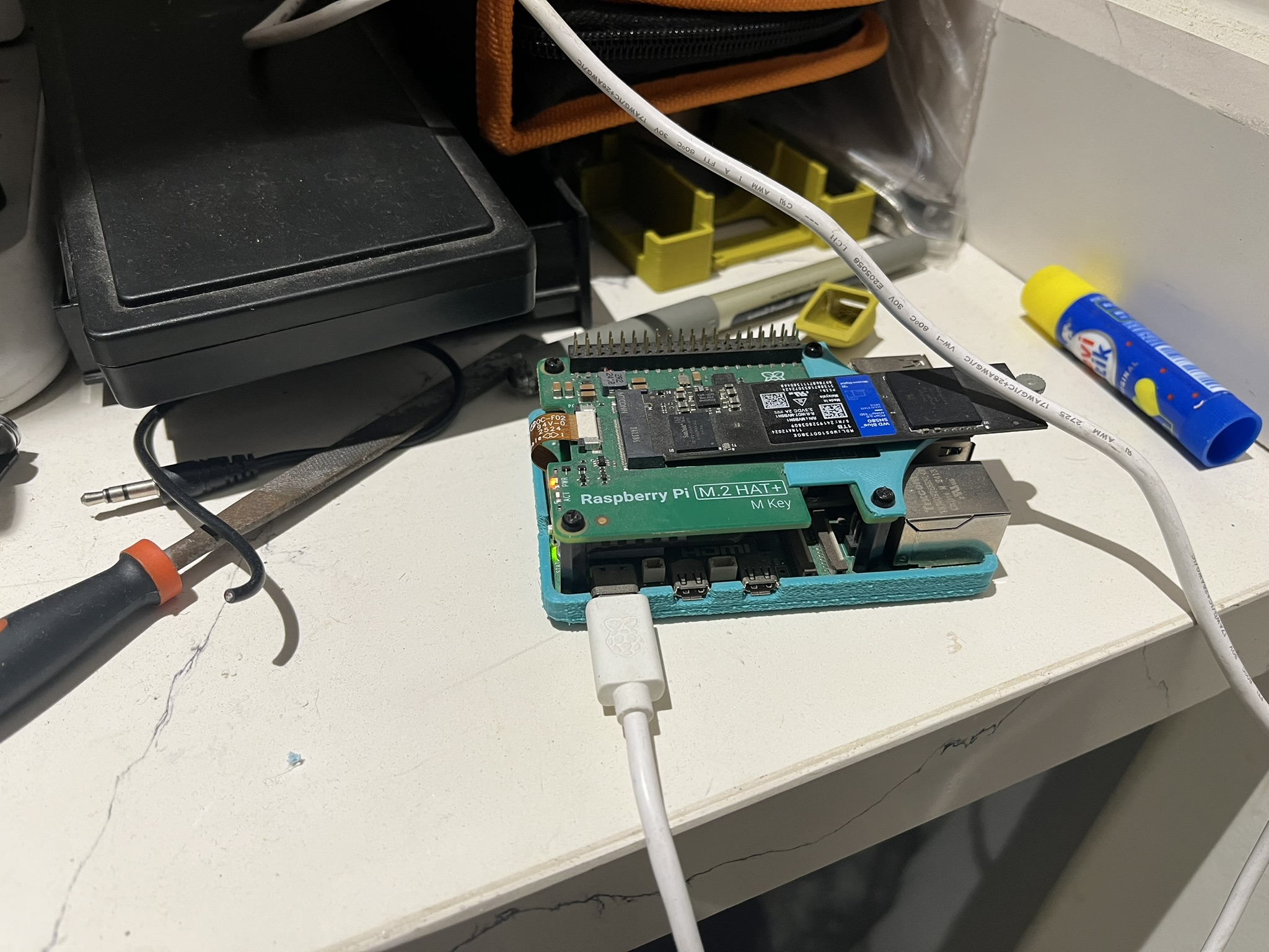
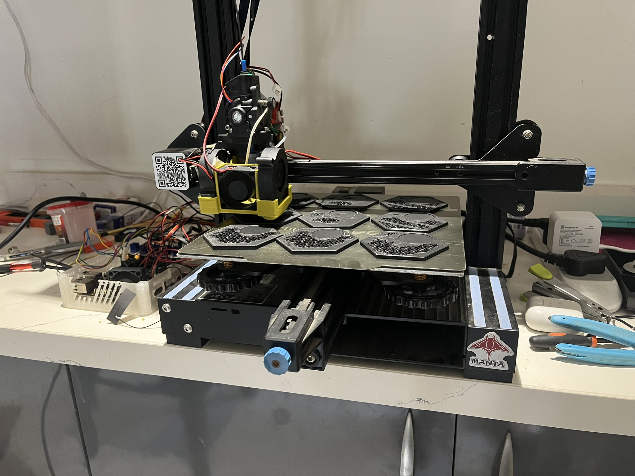
One solution was getting a control board that could run each Z-motor independently. I switched to a Manta M5P, which has five motor drivers—X, Y, E, Z1, and Z2. That suddenly gave me fine control over the entire Z motion system. This upgrade pulled me deeper into Klipper’s documentation as I started exploring how much control the firmware could actually provide.I eventually shifted from an old laptop to a Raspberry Pi clone to act as the primary controller.
The second major step was integrating a Klicky probe into the hotend assembly. This let the printer measure the distance to the bed accurately across the entire surface.
With independent Z motors and a probe, I could now generate a detailed bed mesh to compensate for natural unevenness, automatically square the X-axis gantry before every print and compensate for any tilt introduced when the motors deactivate
The probing routine works like this:
The hotend (with probe attached) moves left to right, taking measurements near each Z motor. Klipper compares the measured distances, then commands each Z motor independently to bring the gantry back to baseline. It does this step-by-step until both sides are perfectly level. That single feature alone stabilized my first layers more than any hardware swap ever could. An elegant software solution to an irreconcilable hardware reality.
With the mechanical inconsistencies resolved, I could finally focus on higher-level motion control.
By mounting an ADXL345 accelerometer to the hotend or the bed, the printer could run controlled vibration sweeps at increasing frequencies on each axis. Klipper uses these measurements to identify the resonant peaks of the X and Y axis. Once identified, it applies an input shaper algorithm developed by the Klipper community to counteract those resonances during high-speed printing.
This was one of the first moments where the printer started behaving like a real robotic system. It was a clear example of how electronic feedback loops directly improve mechanical motion.
Once everything fell into place, I could see the printer as a cousin to CNC mills and robotic arms with their reliance on sensors and feedback loops, the independent motors on different axes, resonance compensation and repeatable motions. They are not rigid bodies, but machines that interact and shape the real world and are in return affected by vibration, heat and material properties, all controlled by software.